

X4.4 Installation & Service Panel Guide
Set up an X4.4 lift from scratch
For qualified installers setting up the lift: learn the service buttons, choose Manual (no limit switches), Physical limit switches, or the Atlantis Position Sensor (APS), and prove the unloaded lift is ready for use.
Connecting your Boater account and app to an installed lift? Use Getting Started.
Qualified installation and service
Make the lift safe before setup
Service settings change how normal controls operate. Complete only tasks you are qualified to perform. Have qualified personnel verify the supply and handle all electrical wiring or internal service; isolate power before opening the enclosure.
- Remove the boat, unload the lift, clear the complete travel area, and use a spotter with an unobstructed view.
- Keep the site disconnect and the normal STOP control immediately accessible during every powered check.
- Lock out power and verify absence of voltage before opening an enclosure, touching wiring, or changing electrical hardware.
- Record the actual supply, installed stopping hardware, physical key, Atlantis Position Sensor (APS), and expected movement direction before changing software choices.
- Finish the mechanical and electrical installation before you enter service mode. On the Physical limit switches path both switches must already be wired by qualified personnel; on the Atlantis Position Sensor (APS) path the sensor must already be installed. A sensor connection light cannot prove that the lift travels or stops safely. Complete the physical tests below.
Panel & signals
Learn the buttons before using them
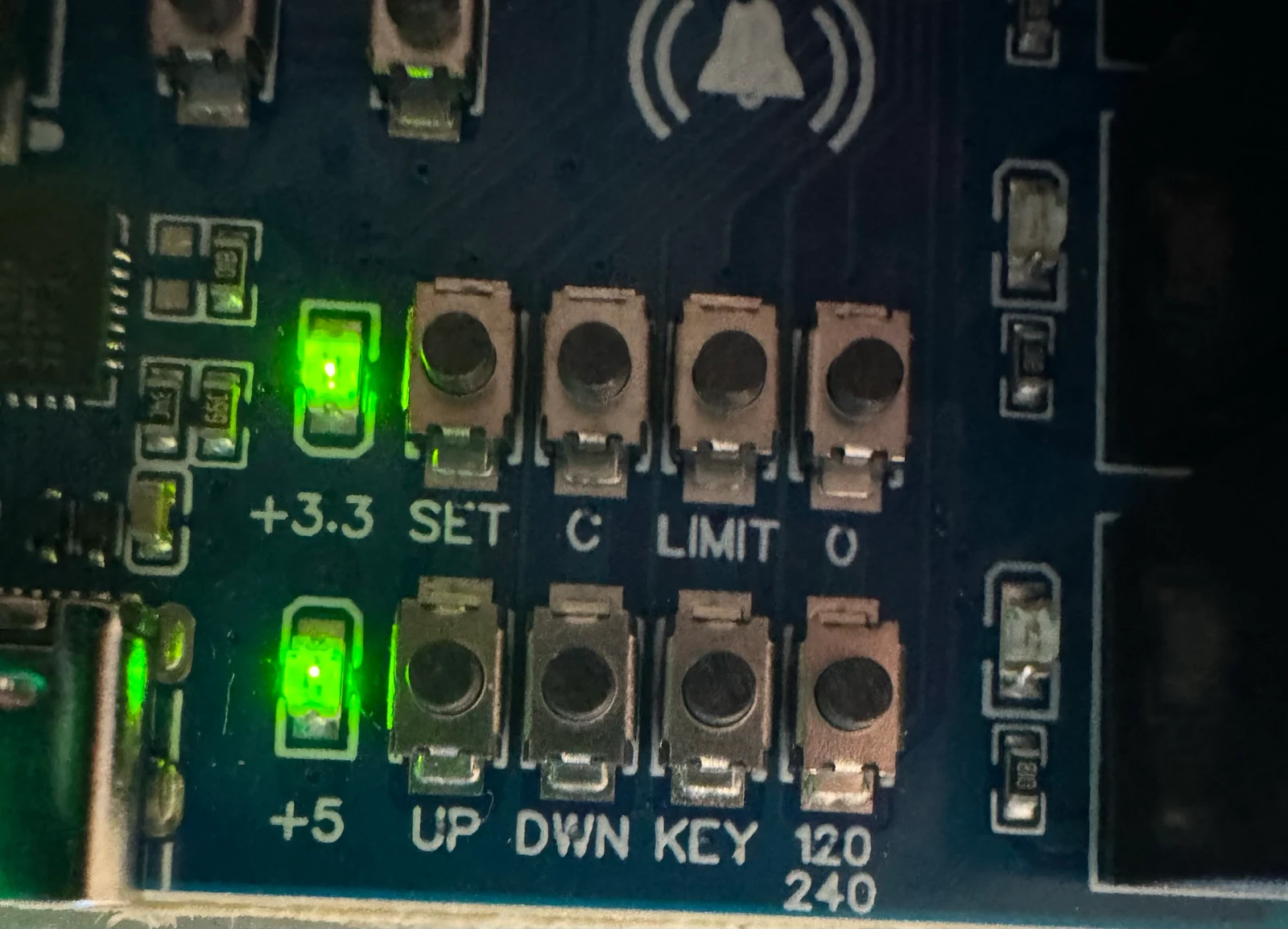
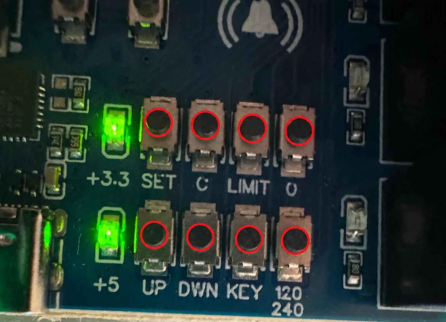
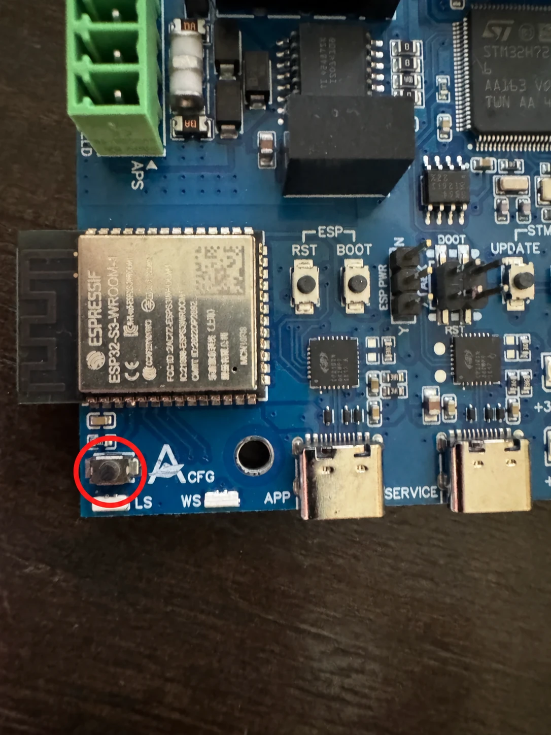
SET opens the menu. A service button selects an action. C confirms only after the light matches the expected color and pattern. Check both the color and whether it blinks, fades, or alternates before pressing C. A short selection beep does not mean the setting has been saved; check the final result too.
Two kinds of buttons appear throughout this guide. The service buttons are the ones on this panel; they only select and confirm settings and never start movement. A normal control — also called a held control — means the lift's everyday UP, DOWN, and STOP controls, the ones the owner uses, including the Atlantis Boater app. Whenever a step says to move or position the lift, use a normal control, not a service button.
- SET
- Open or close service mode
With the lift stopped, hold for two seconds to enter. Cyan fast pulse marks the entry hold; cyan slow breathing and a rising chirp confirm service mode is open. Tap once to leave.
- C
- Confirm the selected action
Press once only after the color matches the intended action. For position capture, wait for the alternating ready pattern before C.
- LIMIT
- Choose the stopping system
The first press shows the saved choice; repeated presses cycle Atlantis Position Sensor (APS), Physical limit switches, or Limits Off — the choice that selects Manual (no limit switches). All use a slow blink: magenta, cyan, or red identifies the choice. C saves it.
- 0
- Set the position-sensor reference
White heartbeat means selected but waiting. At a stopped, stable position it alternates white/cyan to say ready for C.
- UP / DOWN
- Capture protected endpoints
Green or blue heartbeat means selected but waiting. The color alternates with white only when that endpoint is ready for C. Service UP and DOWN never move the lift.
- KEY
- Enable or verify the physical key
Green fast breathing selects key detection on. Red selects detection off. Yellow starts a check of both key positions without changing the settings.
- 120/240
- Save the verified incoming supply
Solid cyan is 120 VAC and solid orange is 240 VAC. This software choice never identifies, converts, or rewires line voltage.
- UP + DOWN
- Measure full-travel movement time
Inside service mode, hold both for two seconds, then release. Teal fast pulse confirms timeout-test selection. C starts warnings; a normal UP control starts the measured run only when ready.
- APP
- Clear setup lockout or confirm an authorized reset
This separate Boater-logo button never uses C and is not part of service mode. Watch the wireless light for its result. Marina-managed lifts remain under marina management after a reset.
Start and finish here
Enter and exit service mode
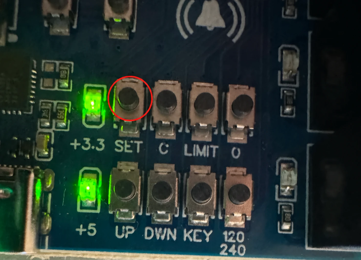
Use the circled SET button to open or close the physical service panel. Hold it for two seconds to enter; briefly press and release it to exit. Use C only to confirm a selected action. Opening service mode does not move the lift. Follow the steps below and check the light and sound each time.
01
Enter
Stop the lift, turn AUTO off, and release every movement control. Hold SET for two seconds. The light fast-pulses cyan during the hold. Release SET when you hear the rising two-tone chirp. Cyan slow breathing means service mode is open. An active APS warning may appear instead; read its meaning before selecting the next action.
02
Select and save
Press the service button for the setting you need. Check its color and pattern, then press C once to confirm. A selection beep alone does not mean the setting saved. For a position capture, release all movement controls and wait for its alternating ready pattern before C.
03
Exit
With the lift stopped, briefly press and release SET. A normal exit gives three cyan flashes and a falling two-tone chirp, then the normal status returns. Saved settings stay saved. An unsaved selection is canceled. If you selected Hardware Zero, AUTO stays off even when you cancel.
During a timeout test, the first service-button press cancels the test and stops movement; it does not also close service mode. Release the button, wait for the canceled result, then briefly press and release SET to leave. During a key check, use SET alone to cancel and leave. A canceled check has its own result tone and light instead of the normal exit cue. If cancellation is refused, keep the lift stopped and contact Support.
First-time setup
One panel. Three installation paths.
Choose the path that matches the installed equipment. Complete the shared preparation, supply, and key steps, then follow the matching stopping-system instructions. Each setup has its own final checks.
Path A
Manual (no limit switches)
LIMIT → red slow blink → C
Held UP/DOWN. Release to stop. Auto, presets, and automatic timeout measurement stay unavailable.
Skip Hardware Zero and endpoint capture.
Open path APath B
Physical limit switches
LIMIT → cyan slow blink → C
Upper and lower switches protect travel. Auto can run to a tested endpoint when enabled for the installation.
Skip Hardware Zero, APS captures, and saved height presets.
Open path BPath C
Atlantis Position Sensor (APS)
LIMIT → magenta slow blink → C
Capture Hardware Zero, the upper endpoint, and the lower endpoint. Then test protected travel and save any presets.
Complete all three captures before Auto or presets.
Open path CStarting here for the first time? Follow the shared steps below before saving a path. Limits Off on the LIMIT button selects Manual (no limit switches), a supported configuration when deliberately specified for the lift; selecting it removes controller-managed endpoint stops.
Setup steps
Configure in this order
Work top to bottom. When an action is refused, read its written reason and specific light pattern before choosing the next step. A refusal tone does not mean a setting saved.
Record
Confirm the installed equipment
Write down Hardware Version X4.4, the software version, incoming supply, Manual (no limit switches), Physical limit switches, or Atlantis Position Sensor (APS); whether a physical key is fitted; and labeled motor direction. The service panel saves choices; it cannot discover wiring or convert voltage.
If the hardware and the evidence disagree, stop before entering service mode.
SET
Enter service mode
Follow the entry steps above: lift stopped, AUTO off, and all movement controls released. Hold SET for two seconds, then release. Continue only after service mode opens and any warning has been checked.
120/240, then C
Save the verified supply first
Press 120/240. The first press shows the saved choice. Press again only when you need to cycle to the qualified, verified incoming supply: solid cyan for 120 VAC or solid orange for 240 VAC. Press C once.
Solid green with three short high beeps confirms the save. A refusal gives a low tone and the applicable issue light. Changing the supply mode restarts KEY detection; always complete the KEY step after this one.
A qualified person must also check and test the actual electrical installation. Choosing a voltage on this panel does not change the wiring or make it safe.
KEY · green and yellow
Match the installed key arrangement
- If a key is installed, enable it: press KEY until it fast-breathes green, then press C. Solid green with the three short high beeps confirms detection on.
- Check both key positions: press KEY until it fast-breathes yellow, then press C.
- Fast-breathing cyan means hold the first key position steady. A fast yellow pulse means move to the opposite position. Fast-breathing magenta means keep holding the second position.
- Solid green with the full success melody is PASS. Yellow/red with a low tone identifies KEY verification failed or canceled. The first position has a 30-second time limit. Changing and holding the second position has a 60-second time limit. Read the result before retrying.
LIMIT, then C
Choose the stopping system
Press LIMIT once to display the saved choice. Press again to cycle choices. Stop at your path's color, then press C once. Physical and Limits Off choices use solid green and three short high beeps. APS uses the connection check below. Continue with the matching branch.
If the displayed result differs from these instructions, keep the lift stopped and contact Atlantis Support with the app message and software versions.
A · Red slow blink · Manual (no limit switches)
Choose Limits Off on the LIMIT button, the choice that selects Manual (no limit switches), for a deliberate held Manual installation. Saving this choice turns Auto off and removes controller-managed endpoint stops.
B · Cyan slow blink · Physical limit switches
Use only when upper and lower physical limit switches are installed. Press C, then test both switches and safe retreat in Step 6.
C · Magenta slow blink · Atlantis Position Sensor (APS)
Use when an Atlantis Position Sensor (APS) is installed. Press C. Three quick green flashes mean the controller can read the sensor. If the controller already knows the sensor is missing, orange/red and a warning sound appear right away. Orange/white means it is still checking. Slower orange/red means the sensor answered earlier but its readings have stopped updating.
Green confirms the connection only. You still need to set and test zero, both stopping points, and movement direction before using Auto. If a warning remains, read the message and have sensor power and wiring checked before continuing. Complete the Step 6 captures and physical checks once the sensor is answering.
Follow your path
Complete the correct stopping branch
Path A
Manual (no limit switches)
- 1. Confirm Limits Off is saved. Limits Off on the LIMIT button is the choice that selects Manual (no limit switches). LIMIT red slow blink → C. Auto is saved OFF and cannot be enabled while limits are off.
- 2. Skip the APS captures and automatic timeout test. Do not select 0, service UP, or service DOWN. There are no saved endpoint stops or height presets in this path.
- 3. Review the movement timeout. The saved timeout still limits a continuous movement. The installer must check or enter an appropriate value through dealer setup — the authorized installer settings in the Atlantis Boater app or the dealer tool. The service panel has no numeric timeout-entry control. The timeout is a backup time limit, not an endpoint stop.
- 4. Exit and test held controls. Tap SET. With normal Manual status blue, hold an ordinary UP control briefly and release; repeat DOWN. Test each installed control and STOP with the unloaded lift. Release well before unsafe travel.
Pass: direction is correct, every release and STOP ends travel, the key arrangement works as specified, Auto remains off, and the owner understands the lift has no controller-managed endpoint protection. Continue to APP setup and final handoff. Fail: leave the lift out of service if a held control fails to stop or direction is wrong.
Path B
Physical limit switches
- 1. Wire the switches before you save this choice. LIMIT cyan slow blink → C. Both the upper and the lower switch must be the Normally Closed (NC) type. An NC switch carries a signal all the time. It drops that signal only when the lift presses it. Buy switches labeled NC. Have qualified personnel install and wire both switches, with power isolated, before you press C. There is no normally-open (NO) selector in this setup.
Incomplete or damaged wiring can make both switches appear pressed. The controller then stops movement in both directions and turns Auto off. Have a qualified person finish or repair the wiring with power disconnected. Keep this stopping system selected; do not switch to Limits Off to bypass the fault. Test both stops before enabling Auto.
- 2. Skip 0, UP, and DOWN capture. These service actions capture APS positions. Physical limit switches establish their stops through their installed positions, not C captures.
- 3. Prove both stops in Manual. Use held normal controls with the lift unloaded. Approach the upper switch carefully, verify it stops UP before unsafe travel, then verify DOWN can retreat. Repeat at the lower switch and verify UP retreat.
- 4. Test the enabled operating modes. Physical limit switches support Auto UP/DOWN to protected endpoints when Auto is permitted for the installation. Complete the timeout procedure below if using automatic measurement. Then exit service mode, enable Auto with the AUTO switch in the Atlantis Boater app, and test each endpoint and STOP while watching the empty lift. If Auto is disabled in installation settings, the dealer must review that setting before offering Auto.
Pass: both switches stop their protected direction, safe retreat works, and every enabled mode stops correctly. Saved height presets and target-position commands require APS and are unavailable on this path. This path is then finished: continue to the movement-timeout measurement below, then APP setup and final handoff. Fail: stop for an open circuit, reversed direction, missing switch, or inconsistent stopping point; repair and repeat the test.
Path C
Atlantis Position Sensor (APS)
Select the magenta slow blink with LIMIT, then press C. Check the sensor lights in Step 5 before moving the lift. A missing-sensor warning does not require a movement attempt. It remains visible while the menu is waiting for your next choice and clears when the sensor answers again. Another service action or a more urgent warning may use the light. Set these positions in order.
Position-sensor branch
- 1. Hardware Zero: press 0 for white heartbeat. Move the unloaded lift to the verified physical top—the intended upper reference. Release all movement, wait at least one second for a steady reading, and wait for alternating white/cyan before pressing C. Pressing 0 has one saved effect right away: Auto is turned off and saved off the moment the white heartbeat appears, before you press C. Cancelling, letting the 30-second selection expire, or a refused capture does not turn Auto back on. Turn Auto back on deliberately once setup is finished and proven, using the AUTO switch in the Atlantis Boater app.
- 2. Upper endpoint: press and release service UP for green heartbeat. Use a normal held control to position the lift at its safe upper stop. Release, wait for steady position, then press C only while the light alternates green/white.
- 3. Lower endpoint: press and release service DOWN for blue heartbeat. Position at the safe lower stop, release, and press C only while the light alternates blue/white.
Setting Hardware Zero clears earlier stopping points and presets and turns Auto off. The lift cannot travel above this top reference after it is set. Set the lower stopping point below the upper one. The controller allows for movement while the motor slows down, so test where the lift actually stops before saving presets.
Hardware Zero and endpoint captures pass only with solid green and the full success melody. A refused capture gives its specific issue pattern and a low tone; read the message and resolve that condition before capturing again.
4. Prove travel and save customer positions. Test both protected stops and safe retreat using held Manual controls. Complete the timeout procedure below when Auto is permitted. Exit service mode. Hardware Zero turned Auto off, so turn Auto back on with that same AUTO switch if Auto is permitted for this installation. Save the desired Preset 1 and Preset 2 positions through installer-authorized app setup if those features will be used, then test each offered Auto endpoint, saved preset, and STOP with the lift empty.
Pass: Hardware Zero and both endpoints are verified, the reported position agrees with travel, both stops protect the lift, and every offered automatic destination passes its empty-lift test. This path is then finished: continue to the movement-timeout measurement below, then APP setup and final handoff. Fail: leave Auto off for any APS, position, direction, or stopping fault.
Solid red at rest identifies an APS direction lock. The lock survives restart and automatic travel stays unavailable. Use the current Direction lock procedure below for qualified diagnosis. Limited held Manual recovery may be available in steps of up to five seconds. It can stop sooner, and other faults can prevent movement. Release the control fully and wait at least one second before another press. A service button still stops live movement.
Solid-red safety lock
Stop first. Prove the cause before changing anything.
This warning means the lift moved the wrong way, or its position sensor reported the wrong direction. The controller stops that move and limits further travel. A qualified technician must identify which problem occurred before making a correction.
Danger — unexpected movement, crush, and electrical hazards
Release the control, turn the physical key OFF if travel is unexpected, and keep Auto disabled. Keep every person, tool, and body part outside the complete travel area. Have qualified personnel secure and unload the lift for recovery; do not move an unsafe lift simply to remove a boat or cycle power to clear the warning.
Qualified, authorized technicians only. Before opening an enclosure or touching motor wiring, disconnect power, apply the site's lockout/tagout procedure, and verify absence of voltage. Keep the normal STOP control and site disconnect immediately accessible during every powered verification.
Direction-recovery risk and liability notice. Unauthorized, unqualified, or improper use can cause serious injury, death, vessel or equipment damage, and may affect warranty coverage. This procedure does not replace applicable codes, site rules, manufacturer instructions, professional judgment, or the Atlantis Terms of Use. To the fullest extent permitted by law, Atlantis Control Systems is not liable for loss or damage caused by misuse of these procedures.
Direction repair for qualified technicians
Owners: leave the lift stopped and contact your installer. These service steps require a qualified technician. If the technician did not see the original move, they can observe a new controlled move as described below. Report the most recent observed move.
- 01
STOP · NOTE WHAT HAPPENED
Keep the lift stopped
Release the control and leave Auto off. Turn the key OFF if movement is unexpected. Note the direction selected, the direction the lift actually moved, and the direction shown in the app. Owners must not repeat an unexpected move to gather this information; leave the lift stopped for the technician.
Solid red - 02
QUALIFIED TECHNICIAN ONLY
Enter service mode with the lift stopped
The following steps are for a qualified technician. Hold SET for two seconds. Cyan/red marks entry; a red heartbeat asks which way the lift physically moved. Keep the lift in sight and the travel area clear. Limited held-button recovery may still be available, but saved stopping points must not be relied on.
Alternating cyan/red (0.3-second cycle)Red direction heartbeat - 03
IF YOU DID NOT SEE THE MOVE
Observe a new controlled move
A qualified technician who missed the original move can observe a new one. With the lift empty, the travel area clear, and Auto off, use a normal held UP or DOWN control for a short move with safe clearance. The service UP and DOWN buttons select an answer; they do not move the lift. Watch the actual travel, release the control, and wait until the lift has fully stopped. Saved stopping points may not protect this move. Recovery is limited to five seconds per move; release all controls for at least one second before another press. If it is unsafe to move, leave the lift stopped.
- 04
REPORT THE MOST RECENT MOVE
Select the direction the lift actually moved
Use the most recent move you watched, not an earlier move that caused the warning. The controller needs a usable sensor reading; a tap with no measurable travel may leave the earlier reading in place. Do not guess if the lift did not move or the sensor is not reporting. With the lift stopped, press and release service UP if it physically went up, or service DOWN if it went down. A slowly fading green or blue light confirms the selection. Check your answer, then press C within 30 seconds.
Green slow breathingBlue slow breathing - 05
REPAIR THE CAUSE
Follow the result shown by the controller
The controller compares the observed movement with the selected direction and sensor reading. Do not guess. Never change sensor direction to hide a lift that physically travels the wrong way.
The lift went the wrong way
Motor wiring needs qualified repair
Yellow/red and the low repair melody identify this result. A qualified technician must disconnect and secure the power, verify it is off, and repair the wiring. After the repair, return to service mode and press C to confirm the work.
Alternating yellow/red (1-second cycle)The lift went the requested way
Check the sensor result
If the sensor reading ran backward, C corrects its direction and checks that the change was saved. If the sensor reading also matched, C confirms the observation and clears the lock. Magenta/red means a sensor correction is pending; follow the service instructions before continuing.
Alternating magenta/red (1-second cycle) - 06
CHECK BOTH DIRECTIONS
Confirm the result and test the empty lift
Solid green and the success melody confirm that the lock cleared. If the controller refuses the change or reports a fault, leave the lift stopped and contact Atlantis Support. The technician must then test both directions with the empty lift in full view.
Solid green - 07
FINISH POSITION SETUP
Restore and test the stopping points
A sensor direction correction requires the position setup to be completed again: Hardware Zero, then the top and bottom stopping points, then presets. Keep Auto off until the technician has finished setup and tested the empty lift, including both stops.
Protected travel test
Measure the movement timeout last
Manual (no limit switches): skip this automatic measurement. Review the saved movement timeout through dealer setup, then continue to APP setup and final handoff. A protected installation with Auto disabled also uses manual timeout entry.
- 1Start fully DOWNBoth protected endpoints or Physical limit switches must already be proven. Position the unloaded lift at its lower stop.
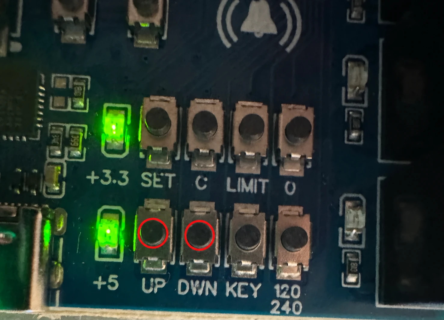
- 2Select the testInside service mode, hold service UP + DOWN together for two seconds. Release both buttons when teal fast pulse confirms the selection.
- 3ConfirmPress C once. Orange fast pulse accompanies the three long warning tones; yellow heartbeat then means release every control and wait for the lift to stop.
- 4Run measured travelThe test temporarily turns on Auto. Blue fast pulse means use the normal DOWN control to reach the tested bottom stop. Green fast pulse means release all controls, then press the normal UP control to start the measured run. Keep the empty lift in sight and use STOP to cancel. The light blinks in the normal movement color during travel.
- 5Verify completionSolid green, the full success melody, and the app completion message confirm the new time was saved. Alternating orange/cyan means canceled; alternating teal/red means paused. Three red flashes and the descending error sound mean the test failed.
Abort: use the normal STOP control or press any service-panel button. APP is not a timeout abort and is not an emergency stop. After any aborted or interrupted run, treat the measurement as incomplete and repeat final validation before handoff.
Separate connectivity control
Connect Atlantis Boater after service setup
APP never uses C and never enters service mode. Stop the lift before touching it; APP does not stop movement and is not an emergency stop. Watch the separate wireless light. The beeper also signals when a Bluetooth lockout clears and when a reset is requested or completed.
A new controller is normally ready to be found by the app without a button hold. Use the five-second action only when Atlantis Boater reports that Bluetooth setup is locked. It does not transfer ownership or reset Wi-Fi.
5 seconds
One magenta blink + high chirp
Release now. Bluetooth setup is unlocked. The existing owner and Wi-Fi settings stay unchanged.
10 seconds
Two magenta blinks
Release now unless an account reset has been authorized. Personal lifts use a 30-second reset hold. Marina-managed lifts require the separate marina procedure below.
30 seconds · residential
Solid magenta for 5 seconds
For an authorized ownership reset only. A successful reset removes the current owner connection and plays a descending melody. The lift must be added to an account again before Bluetooth control works. Wi-Fi is erased after Atlantis confirms the reset. The controller must first have received its personal-ownership information online. If the hold gives no reset confirmation, release it and contact Support. Stopping points stay unchanged. Never use this reset to troubleshoot a connection or warning.
Marina-managed controllers: a 30-second hold does not unclaim them. Authorized marina staff can hold APP for 60 seconds while the lift is stopped and its ownership information is current. Three magenta blinks and a high chirp mean release, then press again within 30 seconds to confirm. The first signal alone does not reset anything. The reset completes only after Atlantis confirms it. The lift stays under marina management; saved Wi-Fi is cleared, and solid magenta with the success melody confirms completion. Contact marina support if any step differs.
Open the complete Wi-Fi guideTest & hand off
Do not load the lift until every check passes
Tap SET to leave service mode. Confirm the falling exit chirp and normal status, then complete the shared checks and the checks for your selected path. Mark the other paths not applicable.
If a movement-timeout test is still running, the first SET tap stops movement and cancels the test. Alternating orange/cyan with a low tone confirms cancellation; tap SET again to leave service mode. If cancellation fails or the expected exit signal does not appear, keep the lift stopped, record the app message and light pattern, and contact Atlantis Support.
- In Lift & Device Info, the Hardware row shows X4.4. Record both firmware versions.
- The saved 120/240 choice matches qualified evidence for the actual incoming supply.
- The saved stopping system matches the hardware physically installed on the lift.
- With AUTO off, every normal held UP and DOWN control moves in the labeled direction and stops immediately when released.
- Manual is solid blue and Auto is solid green. UP blinks and DOWN breathes in the active mode color. A solid-red direction lock has been fully resolved and verified before release.
- Manual (no limit switches): Auto stays off, every held movement stops on release, and the owner understands there is no controller-managed endpoint stop. Record the reviewed movement timeout.
- Physical limit switches or APS: upper and lower protection stop motion before unsafe travel, and the lift can retreat safely from each stop. Test Auto endpoint travel only if that feature will be handed over.
- If a physical key is installed, it passes both positions and produces the expected allowed/blocked behavior. Otherwise record the deliberately selected no-key configuration.
- STOP ends movement. The owner can distinguish normal movement controls from service buttons and knows APP is not an emergency stop.
- APS only: Hardware Zero, both endpoints, and every saved preset have been approached and tested from a safe distance.
- After a controlled power cycle, the lift remains stopped and the saved setup returns. On the APS path, no APS health, zero-required, or missing-endpoint cue remains before owner handoff.
- Service mode is closed, normal status has returned, and no solid-red, alternating orange/red, uncertain, or out-of-bounds result remains.
Pass
Record the serial number, versions, supply, stopping system, endpoint or switch results where fitted, key arrangement and test result, reviewed timeout, APP owner, and installer name for handoff. Record Manual (no limit switches) explicitly when that is the selected path.
Fail
Keep the boat off, leave automatic movement disabled, record the first failed cue, and contact Atlantis Support if the cause cannot be corrected and verified.
Field reference
Every service selection in one table
Use the setup sequence above for the procedure. This appendix is for confirming the selected light and understanding what C will do.
Show complete button, light, and action reference
Atlantis Position Sensor (APS) endpoints
Normal setupC saves APS as the installed stopping system. Three quick green flashes mean the sensor is answering. Orange/red means it is missing or its readings are too old; orange/white means checking. Green does not finish position setup.
Physical limit switches
Normal setupC saves Physical limit switches as the installed stopping system.
Limits Off
Manual installation onlyLimits Off selects Manual (no limit switches): C disables controller-managed endpoints and automatic travel. Use only for an installation deliberately specified and tested for held Manual operation without these limits.
Hardware Zero
APS onlyC establishes the position-sensor reference at the verified physical top after motion is stopped and the reading is steady. Pressing 0 turns Auto off and saves it off right away, before C. Cancelling the selection, or letting it expire, does not turn Auto back on.
Upper endpoint
APS onlyC captures the stopped, steady position as the upper protected endpoint.
Lower endpoint
APS onlyC captures the stopped, steady position as the lower protected endpoint.
Key detection on
Normal setupC enables monitored key sensing for an installation with a physical key.
Key detection off
No-key installation onlyC disables key sensing for an installation deliberately specified without a key. Never use this to bypass a fitted key or failed verification.
Check both key positions
Normal setupC starts the two-position check without changing the key settings.
120 VAC supply
Normal setupC saves 120 VAC mode after a qualified person verifies the actual incoming supply.
240 VAC supply
Normal setupC saves 240 VAC mode after a qualified person verifies the actual incoming supply.
Movement-timeout measurement
Tested stopping systemC begins three warning tones, then waits for stopped and released controls. Nothing else may be running: no app or dealer setup session, and no other measured test. Protected travel and Auto capability must already be configured. APS, when selected, must be trusted.
| Button | Visible signal | Selected choice | What C does |
|---|---|---|---|
| LIMIT | Magenta slow blinkNormal setup | Atlantis Position Sensor (APS) endpoints | C saves APS as the installed stopping system. Three quick green flashes mean the sensor is answering. Orange/red means it is missing or its readings are too old; orange/white means checking. Green does not finish position setup. |
| LIMIT | Cyan slow blinkNormal setup | Physical limit switches | C saves Physical limit switches as the installed stopping system. |
| LIMIT | Red slow blinkManual installation only | Limits Off | Limits Off selects Manual (no limit switches): C disables controller-managed endpoints and automatic travel. Use only for an installation deliberately specified and tested for held Manual operation without these limits. |
| 0 | White heartbeat → alternating white/cyanAPS only | Hardware Zero | C establishes the position-sensor reference at the verified physical top after motion is stopped and the reading is steady. Pressing 0 turns Auto off and saves it off right away, before C. Cancelling the selection, or letting it expire, does not turn Auto back on. |
| UP | Green heartbeat → alternating green/whiteAPS only | Upper endpoint | C captures the stopped, steady position as the upper protected endpoint. |
| DOWN | Blue heartbeat → alternating blue/whiteAPS only | Lower endpoint | C captures the stopped, steady position as the lower protected endpoint. |
| KEY | Green fast breathingNormal setup | Key detection on | C enables monitored key sensing for an installation with a physical key. |
| KEY | Red fast breathingNo-key installation only | Key detection off | C disables key sensing for an installation deliberately specified without a key. Never use this to bypass a fitted key or failed verification. |
| KEY | Yellow fast breathingNormal setup | Check both key positions | C starts the two-position check without changing the key settings. |
| 120/240 | Solid cyanNormal setup | 120 VAC supply | C saves 120 VAC mode after a qualified person verifies the actual incoming supply. |
| 120/240 | Solid orangeNormal setup | 240 VAC supply | C saves 240 VAC mode after a qualified person verifies the actual incoming supply. |
| UP + DOWN | Teal fast pulseTested stopping system | Movement-timeout measurement | C begins three warning tones, then waits for stopped and released controls. Nothing else may be running: no app or dealer setup session, and no other measured test. Protected travel and Auto capability must already be configured. APS, when selected, must be trusted. |
When a panel action needs attention
Alternating magenta/orange
Button conflict
Release all buttons; only exact UP + DOWN is a valid pair.
Orange fast breathing
Selection expired
Reselect and reread the value before C.
Alternating red/orange
Button stuck
Release it; every panel action stays blocked until all service buttons are released.
Alternating green/cyan
Button recovered
Confirm the complete panel is released before continuing.
Alternating red/white
Setting could not be confirmed
Leave the lift stopped and contact Atlantis Support.
Saved setting, except APS selection
Solid green + three short high beeps
APS sensor connection
Three quick green flashes = sensor answering; orange/red = missing or old readings; orange/white = checking
Capture or verification passed
Solid green + full success melody
Refused or KEY failed
Specific issue light + low tone; KEY failure is yellow/red
Timeout canceled
Alternating orange/cyan + low tone; restart the procedure
Timeout failed
Three red flashes + descending error sound; stop
Ordinary service exit
Cyan triple pulse + falling two-tone chirp, then normal status
Setup support
Stop when the equipment, direction, or first result is uncertain
Send Atlantis Support the controller serial number, Hardware and Software Version, selected button and visible signal, app message, installed equipment, and a photo or short video of the first result. Leave the lift stopped until the installer or Support confirms the next step.
Was this article helpful?
Tell us whether this answered your question.