

Finish Lift Setup
A final setup and safety checklist for qualified installers. Use the X4.4 service-panel guide for the setup steps. To connect your app to an already installed lift, use Getting Started.
Safety first
Keep the boat off the lift until every test passes
Keep people and tools clear, use a spotter, and keep the emergency power disconnect within reach. Use held Manual controls for positioning. Run an automatic acceptance or timeout test only after its prerequisites are complete and with the empty lift continuously observed. Isolate power before opening any enclosure or changing wiring.
Start with the right guide
- 1
Boat owner connecting the app
Use Getting Started for your Atlantis Boater account, app connection, and access to an installed lift. Ask the installer to complete installation setup before your first movement.
- 2
Qualified installer setting up the lift
Use the Atlantis Boater Setup Wizard for guided setup in the app, or X4.4 Lift Setup & Service Panel for the physical panel. Both cover Manual (no limit switches), Physical limit switches, and the Atlantis Position Sensor (APS). Carry out only tasks you are qualified to perform; electrical work requires qualified personnel and isolated power. Return here for acceptance and handoff.
Before setup begins
- Remove the boat and keep the cradle, cables, motors, and travel path clear.
- Confirm the lift structure and mechanical equipment are fully installed and ready to move.
- Record the controller serial number and confirm the product label is present and readable.
- Confirm all required controls and safety equipment are physically installed.
- Close all electrical enclosures and make sure the emergency power disconnect is easy to reach before movement tests.
Choose the matching installation path
Use the X4.4 Lift Setup & Service Panel guide for the actual button sequence. Its shared supply and key steps lead into these three paths.
- 1
Path A — Manual (no limit switches)
Select Limits Off with the LIMIT button only for a lift designed to use held Manual controls without automatic stopping points. Auto, saved heights, and automatic timeout measurement are unavailable. Have the installer set an appropriate movement timeout in dealer setup. With the lift empty and a spotter watching, briefly hold UP and confirm the lift rises; release to stop. Repeat with DOWN. If either direction is wrong, stop and have the wiring corrected with power disconnected. Test every installed control, STOP, and the physical key where fitted. The controller cannot check position or direction in this setup.
- 2
Path B — Physical limit switches
Both upper and lower switches must be the normally closed (NC) type. A qualified person must finish the wiring with power disconnected before selecting Physical limit switches. Skip APS position setup. With Auto off, carefully approach each switch: the upper switch must stop UP and allow DOWN; the lower switch must stop DOWN and allow UP. Resolve any wiring warning before continuing. Test automatic travel only if enabled for this installation. Saved heights require APS.
- 3
Path C — Atlantis Position Sensor (APS)
Select APS with LIMIT, then press C. Three quick green flashes mean the controller can read the sensor. Orange/red means the sensor is not answering or its readings are too old; orange/white means the controller is still checking. Wait for the sensor to answer before setting positions. Green does not finish setup: capture Hardware Zero at the verified physical top, then the safe upper and lower stopping points. Test both stops, check the reported height, and prove movement direction. Only after these checks pass should you test any enabled Auto destinations and customer presets.
Final safety checks — every path
- 1
Stop on release
Test every installed manual control. The lift must stop when a held control is released or STOP is pressed.
- 2
Emergency stop
Demonstrate the installed emergency stop or power disconnect and confirm it stops movement as intended.
- 3
Upper and lower protection
For Physical limit switches or APS, confirm each stop prevents unsafe travel and permits safe retreat. For Manual (no limit switches), record this test as not applicable and demonstrate controlled release before unsafe travel.
- 4
Movement timeout
Test the movement timeout, which stops a move that lasts too long. A new controller starts at 60 seconds; the installer must check that this suits the lift. For physical switches or APS with Auto permitted, use the measured-travel procedure in the X4.4 service-panel guide after testing both stops. Otherwise, set the time in the authorized installer settings. The service panel has no numeric time-entry control. Allow enough time for a full empty UP and DOWN run with a suitable margin. A timeout stops the motor and produces a double red flash for about 15 seconds. Explain this to the owner and check the cause before trying again.
- 5
Automatic movement
Test only the automatic features that will be handed over, with the lift empty and continuously observed. For Manual (no limit switches), verify Auto is unavailable and record automatic destination tests as not applicable.
- 6
Power restoration
After a controlled power interruption, confirm the lift remains stopped until a new movement request is made.
- 7
Warnings and faults
Do not hand over the lift while a safety warning remains or the controller keeps restarting. Check that each control moves the lift in the correct direction. Resolve any sensor, position, direction, or switch warning, then repeat the affected tests. Limited movement may remain available during some faults; movement alone does not mean the lift is ready.
Example screens from Atlantis Boater. Names, device details, and settings are samples.
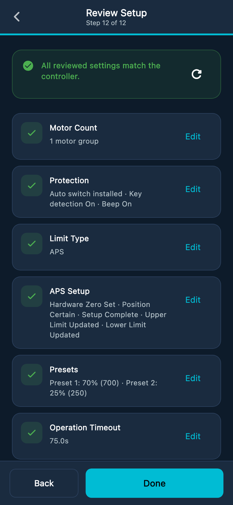
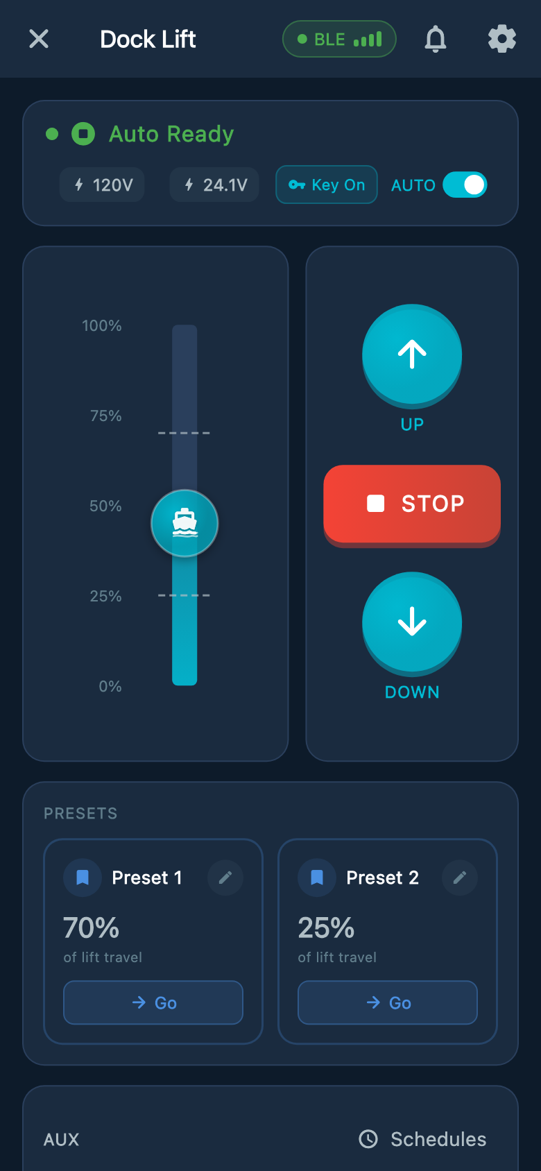
Select an image to enlarge it.
Customer handoff
- Show the owner how to use each control and how to stop the lift in an emergency.
- Explain that the lift must remain in sight whenever it moves.
- Record the selected path. Demonstrate the Atlantis Boater app, normal controls, and only the automatic features supported and tested for this lift.
- Explain the normal ready, moving, attention, and fault indications.
- Show the owner the everyday lights: Manual is blue, Auto is green, a blinking light means the lift is going UP, and a breathing light — one that slowly fades in and out — means it is going DOWN.
- Explain the warnings that apply to this installation. A double red flash after a long run means the movement timer stopped the lift; the light clears after about 15 seconds. The owner should stop and check the cause before continuing.
- Physical limit switches: an alternating cyan/red light means the safety-switch circuit has failed. This fault blocks both directions until the circuit is repaired. Tell the owner to stop using the lift and call for service.
- Atlantis Position Sensor (APS): white/orange, green/orange, or blue/orange means the position setup is incomplete. Solid red while stopped means the direction lock is set and qualified service is needed.
- Alternating orange and red can indicate a position, sensor, or low-power warning. Read the app message and check the Lights and Sounds guide to identify the cause; the colors alone do not identify it.
- With an APS warning, the controller may allow held movement in steps of up to five seconds. This is limited recovery movement, not normal operation. Tell the owner to contact the installer before using it. A qualified technician must resolve the warning and test the lift before normal use.
- Provide the controller serial number, installer contact, service schedule, and warranty information.
- Record the installation date and completed safety-test results.
Was this article helpful?
Tell us whether this answered your question.